Wire Spool Rack
A 10-spool rack generated from the spool measurements, and a hex bore that took two test prints to get right.
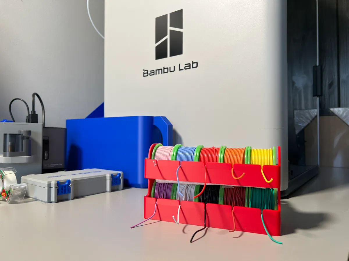
A rack holding ten spools of 22 AWG silicone wire in two rows of five, with the wire feeding out through a notch at each position.
It’s built, and the first assembly was no good — because I left out a part I’d have told you was optional.
It’s a remix of Wire Spool Rack by Grasseus (MakerWorld, CC BY), re-dimensioned for a different spool.
The problem
The original was built around different spools. Mine are BNTECHGO 22 AWG silicone — 48 mm flange outside diameter, 33 mm wide, with a hex bore running all the way through.
Changing the spool changes almost everything else. The pitch between positions, the overall width, the height of both rows, where the rods sit, how far the front wall stands off. Scaling the original uniformly wouldn’t work, because only some of those dimensions depend on spool diameter and the rest depend on width, wall thickness or clearance.
That’s the case for not drawing it.
Design
The rack is generated by a Python script using manifold3d. The measured spool goes in at the
top, and every other dimension is derived:
SPOOL_D = 48.0        # flange OD
SPOOL_W = 33.0        # overall width
N_PER_ROW = 5
GAP = 1.5             # gap between spools and at walls
T = 3.0               # wall / floor / lip thickness
CLR_BOT = 2.5         # clearance under each spool (floor / between rows)

PITCH = SPOOL_W + GAP
INNER_W = N_PER_ROW * SPOOL_W + (N_PER_ROW + 1) * GAP
W = INNER_W + 2 * T
Nothing in the model holds a literal width. W falls out of the spool width, the count and the
gap, so changing to a different spool is a few edits at the top of the file and a re-run — not a
redraw. Running python wire_rack_Rev1.py <outdir> regenerates the rack, the plug plate and the
fit test together, which matters because they have to agree with each other.
The resulting Rev 1 geometry:
| Feature | Value |
|---|---|
| Outer size | 180 W × 68 D × 104 H mm |
| Walls, floor, lips | 3 mm |
| Spool pitch | 34.5 mm, centres at 21 / 55.5 / 90 / 124.5 / 159 mm from the left |
| Rod holes | Ø2.2 mm for 2 mm rod, 26.5 mm in from the back, 29.5 mm and 80 mm above the bottom |
| Wire notches | 1.4 mm wide × 8 mm deep, R2.5 entry, one per spool |
| Sponge shelf | 8 mm, top at 60 mm |
A couple of those numbers are not obvious. The notch is 1.4 mm for wire measuring roughly 1.6–1.7 mm outside diameter, so the silicone has to deform slightly to go in and then stays put. And the sponge shelf has a 45° underside, which is the angle at which a print stops needing support underneath it — the geometry is shaped by the process, so the only supports anywhere in the job are tree supports under the upper front lip.
The sponge itself isn’t padding. It’s a brake: two strips, roughly 172 × 20 × 20 mm, pressing against the spools so they turn under a pull and stop when you stop pulling. More on that below, because it’s the part I underestimated.
What the testing showed
The hex bore measurement couldn’t really be calculated. The bore is hexagonal, runs right through, and has rounded corners, so the number that matters is across the flats — and a plug that’s slightly too small falls out while one slightly too large won’t seat.
So I printed a ladder instead of guessing, each rung marked with raised dots so they stay identifiable once they’re loose on the bench.
| Test | Sizes across flats | Result |
|---|---|---|
| Fit test 1 | 17.0 / 17.2 / 17.4 mm (1–3 dots) | All three drop straight through. Too small. |
| Fit test 2 | 17.6 / 17.8 / 18.0 / 18.2 mm (1–4 dots), corners clipped to Ø19.8 | 17.8 mm is a firm thumb-press fit with no movement. |
The first sweep missed entirely — every candidate was undersized, which is worth recording because it says the initial estimate was out by more than the range I’d bracketed. The second sweep also changed the geometry rather than only the size, clipping the corners to Ø19.8 so they clear the bore’s rounded corners instead of fighting them.
17.8 mm then went back into the source as a parameter, and the production plate of twenty plugs came off that. Two test prints to replace a guess with a measurement.
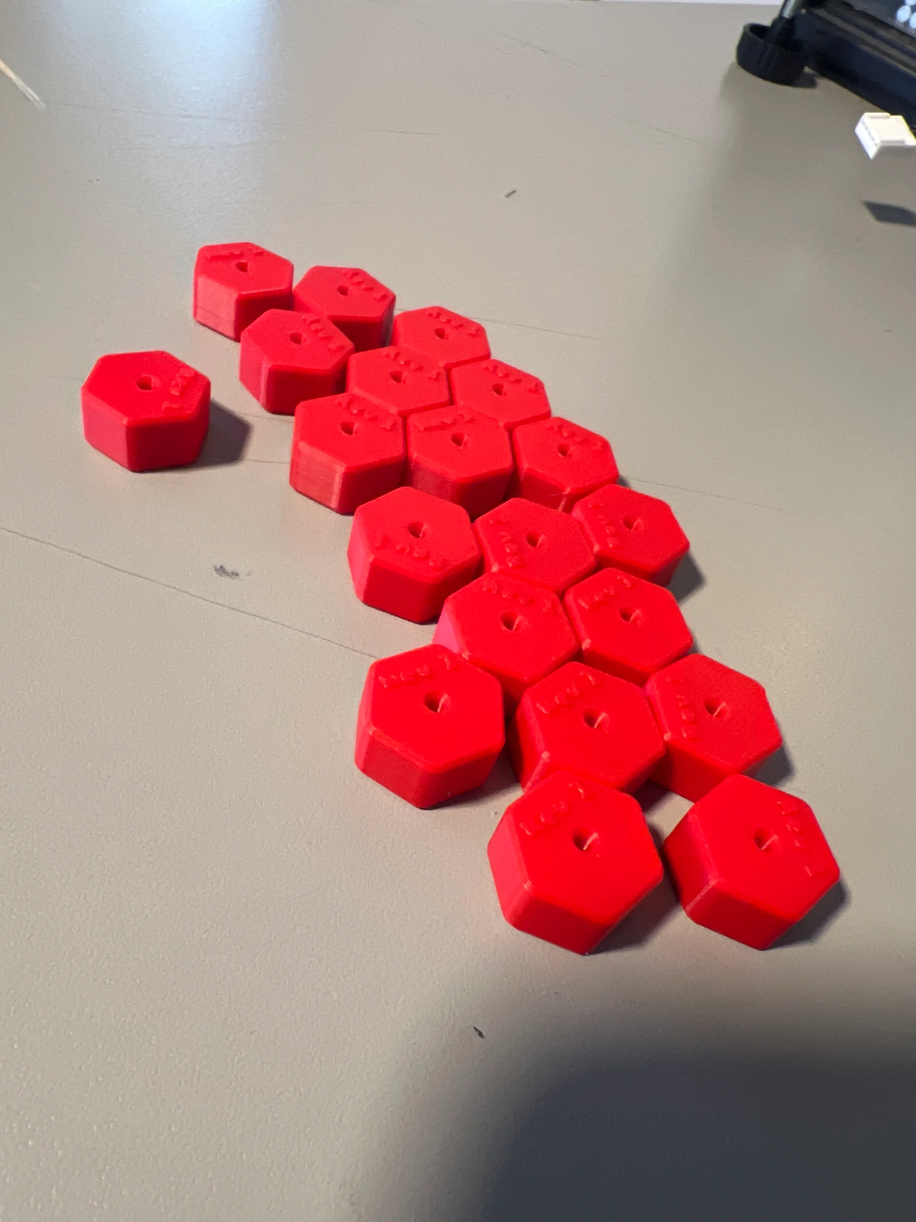
Each plug is 10 mm long with a Ø2.4 mm hole for the rod, and carries “Rev 1” raised on one end. The label is on the inner end deliberately — pushed in that way round it faces the spool rather than the next spool along, so it can’t rub.
What the build showed
Two things went wrong, and they turned out to be the same thing. Most of the rest held up.
The sponge wasn’t optional
I assembled it without the sponge strips. On paper they’re the least interesting thing in the bill of materials — two bits of foam, no dimensions that have to be right, nothing that interacts with the printed geometry. So they were the obvious thing to skip to get it on the wall.
It was useless. Ten spools free on two rods with nothing to resist them: pull a length of wire and the spool keeps turning after you stop, paying out slack that tangles with its neighbours. The rack held the spools perfectly well and failed completely at the actual job, which is dispensing wire.
Fitting the strips fixed it. They’re the whole mechanism — the rods just locate the spools, and the friction is what makes it work.
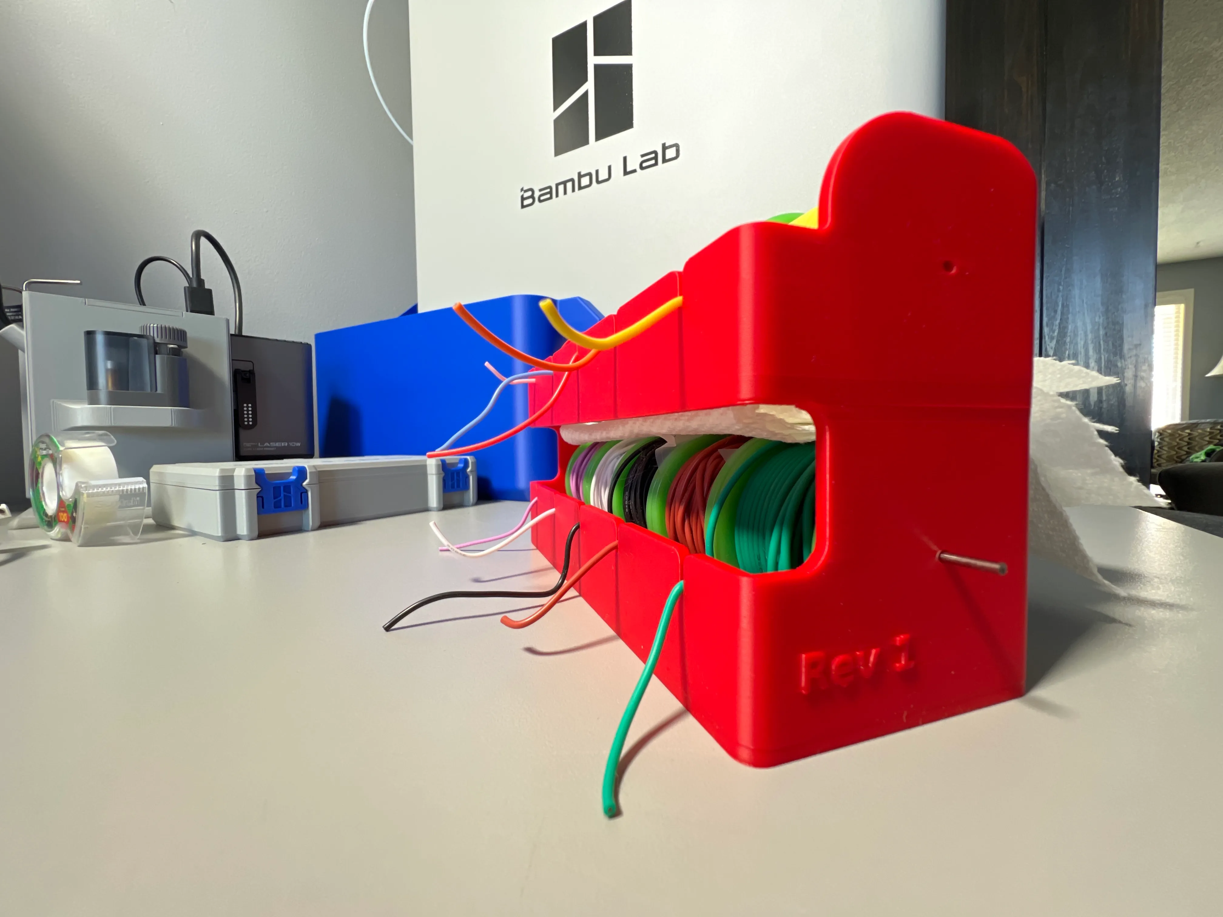
That white strip between the rows is the entire difference between a rack and a tangle.
The rods changed while I was holding them
The design called for 2 mm rods cut to 180 mm, flush with the outer walls, and glued. That makes a clean-looking object. It also makes one you can never reload — a glued, flush rod has nothing to grip and nowhere to go, so changing a spool would mean destroying something.
I noticed that with the rod in my hand, and left them long and unglued instead. They stand proud of the wall by a few millimetres, which is enough to pull them by. Spools come off and go back on in about ten seconds.
It’s a slightly less tidy object in exchange for one that can be maintained, and I’d make that trade every time. It’s also not a decision I’d have reached at the screen: on the model, “flush and glued” reads as finished, and the cost only becomes obvious when you’re the one who’ll have to reload it. Several reloads later it still works the way I wanted it to.
What I hadn’t anticipated is that getting the rod in is the fiddly part. With a full row loaded, it has to pass through the near wall, then ten plug bores at Ø2.4 mm, and then find a Ø2.2 mm hole in the far wall — everything nominally coaxial, nothing visible once you’re halfway across. It goes, but it takes patience, and it’s worse the fuller the rack is.
That’s a Rev 2 problem rather than a Rev 1 fault. The fix is probably a lead-in — a chamfer on the far hole, or a tapered rod end — so the last few millimetres stop being a blind search. I haven’t decided which.
What held up
The predictions that didn’t need changing are worth recording too, because an untested number and a confirmed one look identical in a model:
| Prediction | Outcome |
|---|---|
| 1.4 mm notch retains 22 AWG silicone without damaging it | Holds. No stripping or skiving of the insulation in use. |
| 1.5 mm clearance lets spools turn without fouling | No rubbing between neighbours. |
| Ø2.2 mm hole gives a workable fit on 2 mm rod | Slip fit by hand, pulled and re-racked several times. |
Two things are still open. How far the rods should stand proud is currently whatever felt right rather than a dimension. And I have no figure for how far the sponge is compressed, which is the one number that actually sets the brake force — see below.
What I actually take from this
Both of those are the same failure, and it isn’t a failure of dimensions.
The printed parts had tolerances, test prints and a revision log. Every number in them could be defended. The sponge had a size and no reason attached, so I read it as packaging and left it out. The rods had an instruction — flush, glued — and no reason attached either, so nothing in the files pushed back when that instruction turned out to cost me the ability to reload the thing.
In both cases the design intent was real and correct. It just lived in my head rather than in the model, which is the one place it can’t be checked, argued with, or acted on by anyone else — including me, three weeks later, with a rod in my hand.
A dimension without a reason attached is a dimension someone will eventually decide to ignore. Both of those are going into the source as comments, beside the numbers they explain.
The same gap is already open again, which is the uncomfortable part. The brake is the mechanism, and I still have no figure for how hard it presses — only a strip size. Build Rev 2 with the same foam cut to the same dimensions but half the squeeze and you’d get a rack that freewheels, with nothing in the files to say you’d done anything wrong. Measuring that compression is the next thing to do, and it’s exactly the lesson above, one revision later.
Files
| File | What it is |
|---|---|
wire_rack_Rev1.py |
Parametric source (Python + manifold3d). Regenerates the rack, the plug plate and fit test 1. |
Wire_rack_10_spool_Rev1.3mf |
Rack, ready to slice. Print upright, tree supports under the upper front lip only. |
Hex_plug_Rev1_x20.3mf |
Production plugs, 20 off, 17.8 mm across flats. |
Hex_plug_fit_test.3mf |
Fit test 1 — 17.0 / 17.2 / 17.4 mm. All too small. |
Hex_plug_fit_test_2.3mf |
Fit test 2 — 17.6 / 17.8 / 18.0 / 18.2 mm. 17.8 wins. |
Bill of materials, as built: one printed rack, twenty hex bushing plugs (two per spool), two 2 mm steel rods left over-length and unglued so they can be pulled to reload, two sponge strips at roughly 172 × 20 × 20 mm. Rev 1 as designed specified the rods at 180 mm, flush and glued; see above for why that changed on the bench.
Original design: Wire Spool Rack by Grasseus, published on MakerWorld under CC BY 4.0. This version is re-dimensioned and re-implemented as a parametric script; the original file is kept alongside the source for reference and attribution.